
")
")
")
")
")
")
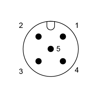
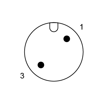
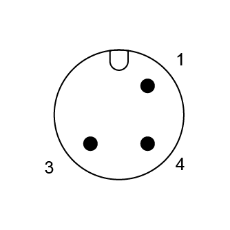
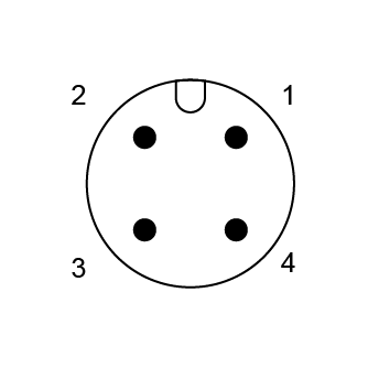
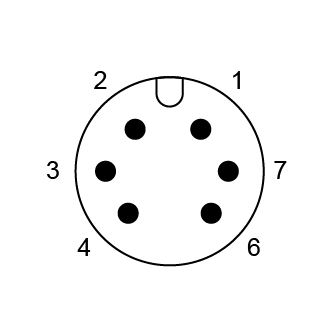
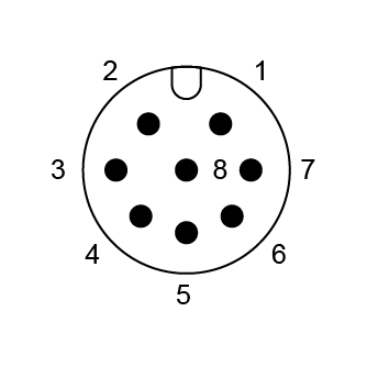
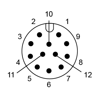
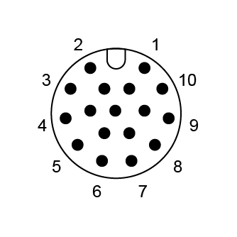
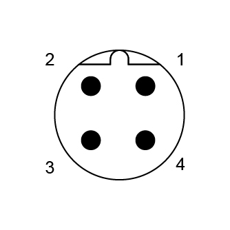
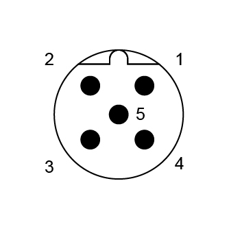
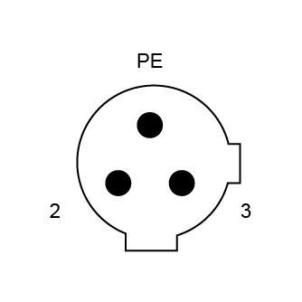
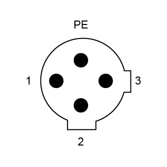
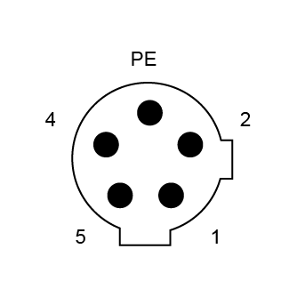
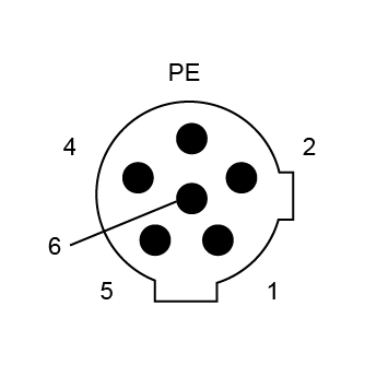
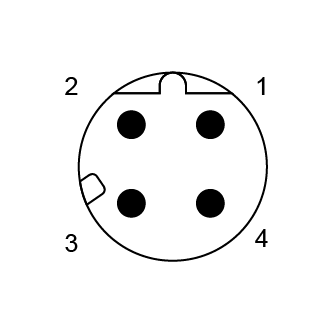
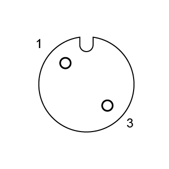
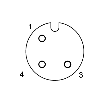
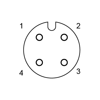
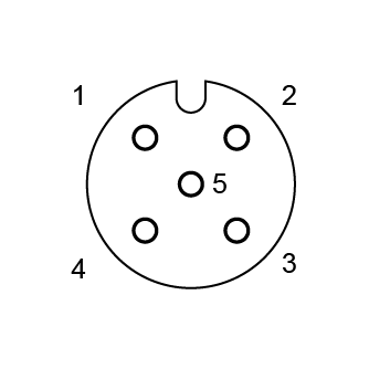
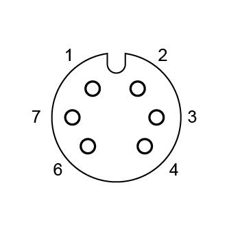
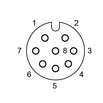
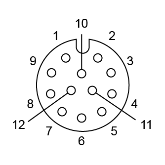
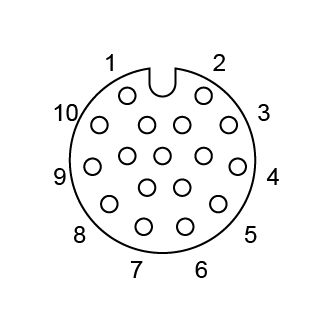
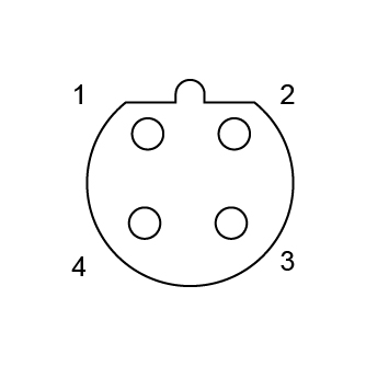
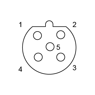
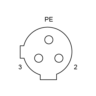
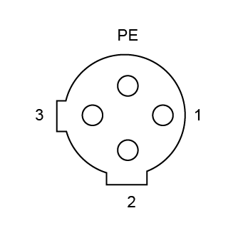
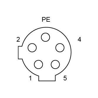
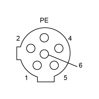
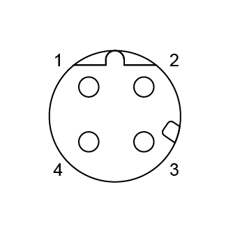
Core Count : 2P, 3P, 4P, 5P, 6P, 7P, 8P, 12P, 17P
Category : Male
Installation Method : Soldering Type
Connection Method : Panel Mounting
Applications : Power, Signal
Front Lock Structure: The M12 board front-mounted connector adopts a front-lock design. The threaded locking can be completed from the front panel surface, without needing to touch the internal wiring of the equipment. It is particularly suitable for scenarios where the internal wiring space is limited, such as sensors and small control cabinets. Multiple installation forms: Common ones include soldering wire type and PCB type. For the soldering wire type, attention should be paid to the soldering temperature, and generally, a temperature range of -40 to 85℃ is recommended.
Protection Level: Industry standard IP67 protection level. Some products can reach IP68, which can be immersed in 1 meter of water for 30 minutes without leakage, effectively resisting environmental factors such as outdoor rain and dust splashing in the workshop. Application Scenarios: Suitable for scenarios such as automation control cabinet panels, outdoor intelligent sensors, and small outdoor equipment. Especially suitable for industrial connection requirements with limited internal wiring space, needing to withstand harsh environments or frequent vibrations.
|
Product model
|
Core
|
Rated current
|
Rated voltage
|
Wire gauge / Dimension
|
||
|
A/C
|
D/C
|
AWG
|
mm²
|
|||
| MC12AM-02F2LSLNS301 |
2
|
4A
|
250V
|
250V
|
22
|
0.34
|
| MC12AM-03F2LSLNS301 |
3
|
4A
|
250V
|
250V
|
22
|
0.34
|
| MC12AM-04F2LSLNS301 |
4
|
4A
|
250V
|
250V
|
22
|
0.34
|
| MC12AM-05F2LSLNS301 |
5
|
4A
|
60V
|
60V
|
22
|
0.34
|
| MC12AM-06F2LSLNS301 |
6
|
2A
|
30V
|
30V
|
24
|
0.25
|
| MC12AM-08F2LSLNS301 |
8
|
2A
|
30V
|
30V
|
24
|
0.25
|
| MC12AM-12F2LSLNS301 |
12
|
1.5A
|
30V
|
30V
|
26
|
0.14
|
| MC12AM-17F2LSLNS301 |
17
|
1.5A
|
30V
|
30V
|
26
|
0.14
|
| Core | 2A | 3A | 4A | 5A |
| male end |
|
|
|
|
| 6A | 8A | 12A | 17A | |
|
|
|
|
|
|
| 4B | 5B | 3C | 4C | |
|
|
|
|
|
|
| 5C | 6C | 4D | ||
|
|
|
|
||
| Core | 2A | 3A | 4A | 5A |
| female connector |
|
|
|
|
| 6A | 8A | 12A | 17A | |
|
|
|
|
|
|
| 4B | 5B | 3C | 4C | |
|
|
|
|
|
|
| 5C | 6C | 4D | ||
|
|
|
|
|
The connector must not be plugged or unplugged under load. Failure to follow the instructions and improper use can result in personal injury.
The development of the connector is aimed at being applied in factory engineering, control and electrical equipment construction. Users are responsible for checking whether the connector can also be used in other applications.
Connectors used in circuits with dangerous voltages that cause electric shock must be installed and used only by personnel who have received training in electrical engineering, or under their supervision, while taking into account the applicable regulations and standards.
Users must take appropriate security measures to ensure that the connectors do not accidentally disconnect.
When installing, apply moderate force and use the special tool to tighten the nuts. Avoid excessive force to prevent the shell from deforming or the pins from bending. Ensure that the plug and socket are fully engaged. Do not power on the device when not locked in place to prevent arc discharge due to poor contact.
The plug connectors with an enclosure protection rating of IP67 and IP68 are not suitable for use in water. When used outdoors, the plug connectors must be protected against corrosion separately. For further information on IP protection ratings, please refer to "Technical Information".

M12 A Coded Connection Cable Straight Overmolded Type 2-17PIN Female Solder Type

M16 Circular Connector Rear-Panel Mount 2–24 PIN Male Soldered Type

M12 A Coded Connectors Board Front Mount 2-17PIN Female Solder Type M12*1.0

M12 A Coded Connectors Board Front Mount 2-17PIN Male Solder Type M12*1
 telephone
 Contact US